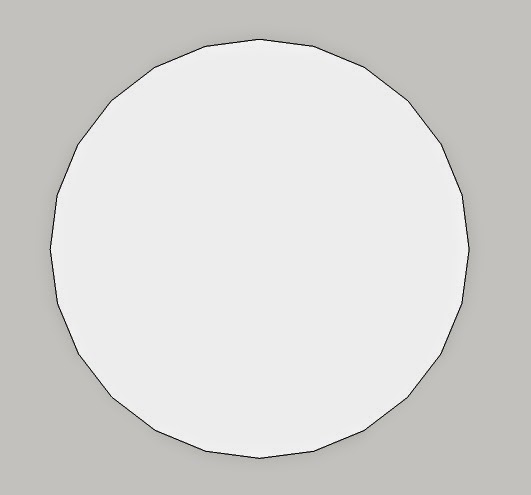
1. Start by making a circle.

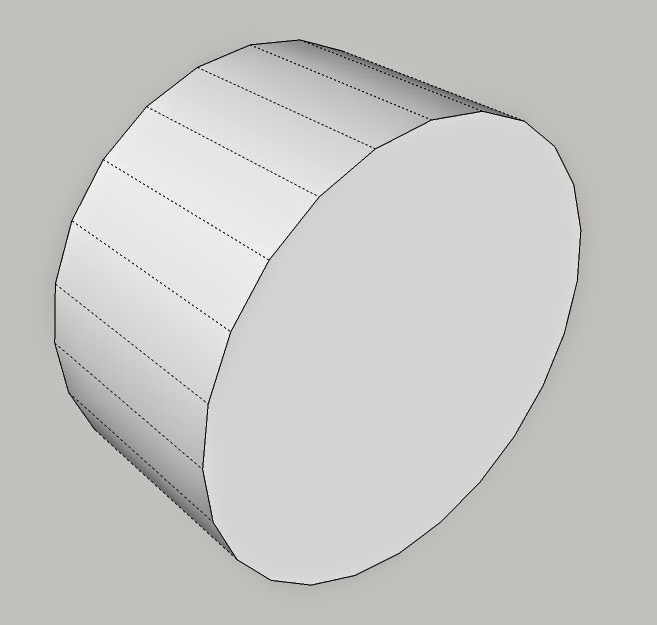
2. Use the Push/Pull Tool to extrude the circle to the thickness you want the tire to be. I'm making this one a little thicker than normal for sake of demonstration.

3. You'll notice that the default circle in Sketchup is actually just a 24-sided polygon (also known affectionately as an "icosikaitetragon". Pay close attention; there will be a quiz on this at the end). Select one or two of the 24 faces of your extruded circle, right click, and select "Create Component". Make sure that the "Replace selection with component" box is checked.
4. This is what the component-ized face should look like. I chose two of the faces to form my component so that I could have two slightly offset tread patterns, but you can just as easily make just one face into the component and have a nice repeating pattern all the way around.
5. With the component selected, choose the Rotate tool. We're going to use this to copy the component all around the outside of the wheel. If you pan across the center of the side of the tire, the Rotate tool should eventually snap to the centerpoint (a.k.a., the "focus") of the circle. Click on that point, press the CTRL key, and then click on the center or one of the corners of the component; drag it around until the measurements box shows you've reached 330º (if you've made your component using two faces) or 345º (if you've opted to use only one face in your component).
6. Once you've drug the component around the circle and left-clicked it into place, you'll want to type in a 11/ (for a 2-face component) or 23/ (for a single-face component) and hit enter. The slash tells Sketchup that you want to copy the component the number of times you specify by the number. The image below shows how the one component was copied all around the tire.
7. Now it is time to sculpt the rounded sidewalls that make a flat disc look like an actual tire. There are a couple ways of doing this, such as by using the Follow Me tool, but I'm going to show just one method. Start by selecting the Offset tool (shown below) and pulling in several circles from the original.
8. Now select the middle circles as shown below.
9. With those circles selected, choose the Move tool, click on the circles, and then press the Right Arrow key on your keyboard. This forces the circles to move only along the Red axis; the same can be done with the Left Arrow key for the Green axis and the Up or Down Arrow keys for the Blue axis. If you don't do this, the selected circles will simply slide around on the face of the disc, but by forcing them to move only along the Red axis, you can get them to pop out, like this:
10. Now we'll do the same thing again, only this time we'll select only the middlemost circle and we'll only pop it out half as far. This gives it a fairly rounded appearance, and works well for wheels in scales up to 15mm or so. For 28mm and larger, you may want to go with an additional set of circles popped out half as much as our second one.
11. You can follow the same process as above for the other side, or you can simply copy, paste, and flip the one you just made.
12. Now it's time to make the rims. There are so many ways of doing this, but for a military vehicle, I find that one with big hex-head bolts looks pretty good.
13. Once you've sketched out your rim details, then you can pop them in or out using the Push/Pull tool.
14. Now we'll go make up some tread, and this is where the magic of components comes in. The beauty of making something that you'll need a lot of into a component is that you can make changes that will then be replicated across all the copies of that component in your work space. Begin by right-clicking one of the components and choosing Edit Component.
15. For this example build, I'm going to make something reminiscent of a Humvee tire, like these:
16. Now just draw some kind of tread pattern that you find to be cool, like such. After I drew these, I shifted the patterns slightly, one left and one right, to give my tread that kind of ziggedy-zaggedy feel. Again, you only need to do this on the one or two faces in the component, and the rest of the components will follow suit.
17. Once you've drawn out your tread pattern, you can then pop out the individual pieces using the Push/Pull tool.
18. As a final touch, I like to give my tread a bit of an overhang, which you sometimes see on mudding and off-road tires. Once I've created the overhang, then I go inside the tire and delete any lines or faces which happen to be trapped inside the treads. This is for the sake of 3D printing; if you leave those hidden faces and lines, you may have models rejected for having "unintentional loose shells".
19. Here is our finished tire! Not the best I've ever made, but good enough to demonstrate the technique.
Here are some other tire designs I've made in the past. This one is an homage to the tires on the old M35 "deuce-and-a-half" trucks I drove when I was with the 2nd Infantry Division in Korea:
Here is it with the hidden geometry shown, so you can see the curvature better:
These tires were made for 40k players to use in modding their own vehicles. They're wholly impractical, but hey -- it's 40k. Nothing makes any practical sense.


Nice
ReplyDeleteHi,
ReplyDeletestumble accross you blog, I trying out this but I can't get the same result for step 6.
using skecthup make v15
Sorry, Zuan! I missed a step!
DeleteIn Step 5, when you click on the center mark and then on the component, you need to press CTRL when clicking on the component. A small "+" will appear next to your cursor; this signifies that you aren't just moving the component, but making a copy of it. Then, in Step 6, you use the "/" notation to tell Sketchup how many copies to make.
Sorry for the omission!